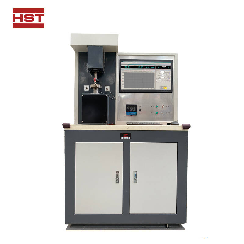


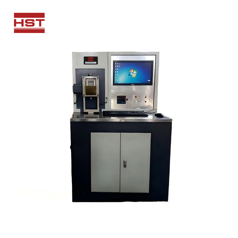

HST-MRH-3 High Speed Ring-Block Wear Testing Machine
HST-MRH-3 High Speed Ring-Block Wear Testing Machine
मानकों:
एक उद्धरण का अनुरोध करें फ़ाइलें डाउनलोड करेंApplication Range
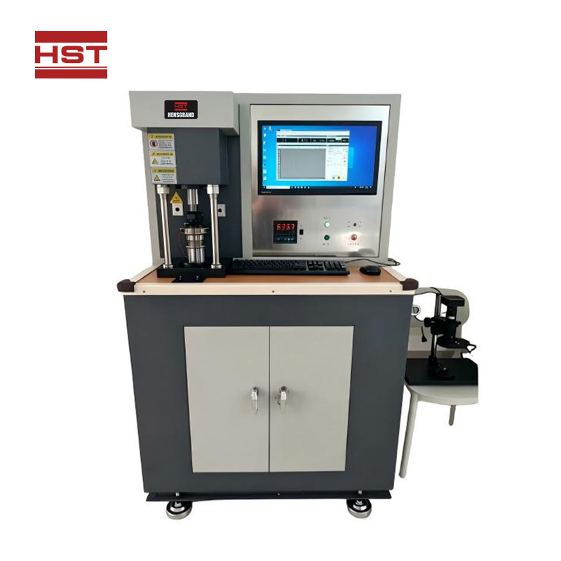
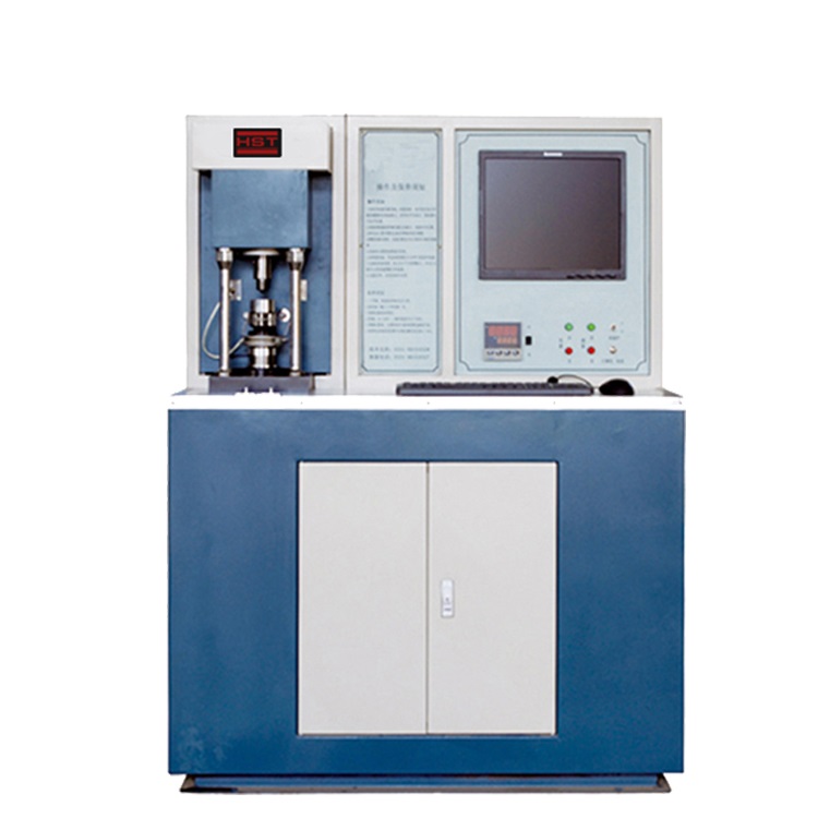
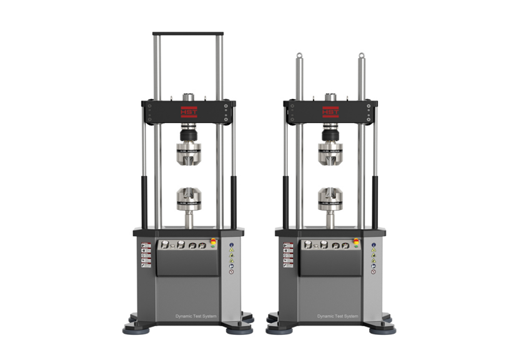
The high-speed ring-on-block friction tester is mainly adopted for the performance research of various metals, non-metallic materials and coatings. It can also test the lubricating properties of different lubricating oils and greases, and is especially suitable for evaluating the anti-scuffing performance of medium and high-grade automotive gear oils, such as the simulation assessment of anti-scuffing performance for GL-3, GL-4, GL-5 and other grades.
This friction and wear tester is specially designed for universities, research institutes and manufacturing enterprises. Drawing on advanced domestic technologies for the design of its main machine and auxiliary fixtures, the tester features an attractive appearance, easy operation, as well as stable and reliable performance.
Specification
Parameter | Specification |
Maximum Test Force | 3000N |
Maximum Measurable Friction Force | 300N |
Spindle Speed Range | 200~4000r/min, stepless adjustable |
Test Oil Temperature Range | Room temperature~100℃ |
Time Display & Control Range | 10~9999s(min) |
Standard Test Ring Dimension | Φ49.22mm × 13.06mm |
Standard Test Block Dimension | □12.32mm × 19.05mm |
Structural Features and Working Principle of Ring-on-Block Friction and Wear Tester
The structure of the main unit is shown in Figure 1. The main unit is composed of a spindle drive system, test oil chamber and temperature measuring device, friction force measuring device, loading lever, test force measuring device and other components, all of which are mounted on a welded base.
1 Structure and Working Principle of Spindle Drive System
Figure 1 illustrates the structural layout of the spindle transmission and test chamber.
The friction pair of this tester adopts a ring-on-block configuration. The test ring (4) is mounted on the front end of the spindle (15) and rotates at a set rotational speed together with the spindle. The spindle is driven by a three-phase asynchronous motor via an arc toothed timing belt (13), driven pulley (9) and driving pulley (14). The motor is controlled by a variable frequency governor, enabling stepless speed adjustment within a specified range. Component (12) is the tension pulley, which adjusts the tightness of the toothed timing belt.
A magnetoelectric sensor (11) fitted to the rear end of the spindle measures the spindle rotational speed and revolution count, with readings displayed on the speed and revolution meter of the control cabinet.
Spindle bearings (18) and (19) are normally lubricated with lithium-based grease. If the 2:1 speed-increasing attachment is used, lubricating oil must be adopted for lubrication.
2 Test Oil Chamber and Temperature Measuring Device
The wear test is conducted inside the oil chamber. An oil filling port is arranged on the top of the oil chamber body (6). The test oil can be measured using the graduated cylinder supplied with the equipment; generally, only enough oil to submerge the friction surfaces is required. After the test completes, the oil can be drained from the drain nozzle (3) at the bottom.
For room-temperature testing, the chamber door (16) is made of transparent plexiglass, allowing clear observation of the internal test process. For high-temperature testing, a heater is installed on the stainless steel chamber door to heat the test oil. A platinum resistance sensor (2) mounted beneath the chamber measures the oil temperature, and a temperature controller realizes automatic closed-loop temperature regulation.
3 Friction Force Measuring Device
As the test ring rotates with the spindle, friction force is generated between the test ring and test block. This force presses against the friction force sensor (8) via the ejector rod (10), and the measured value is displayed on the friction force indicator.
4 Loading Lever and Test Force Measuring Device
Figure 2 shows the structural drawing of the loading lever.
The test force applied to the specimen is under closed-loop control by a stepper motor (1) and speed governor. When the motor rotates forward, it compresses the compression spring (2). Via the bonded support (4), a downward force is generated at the left end of the 1:3 loading lever (3). This force pulls the crossbeam downward through the test force sensor (5) and tension plate (6). Since the test block is mounted on the lower part of the crossbeam, compressive load is produced between the test ring and test block.
The compressive load between the test ring and test block is measured by the test force sensor and displayed on the test force indicator. The target test force can be preset and fed back through the stepper motor control system to achieve closed-loop control.
संबंधित उत्पाद